
Regal 3D Print to Cast Guidelines
Use these guidelines when preparing jewellery designs for 3D printing and casting.
Common Design Issues
- Exporting STL files and mesh density.
- Mesh and file faults.
- Investment breakage.
- Sharp edges.
- Holes and gaps.
- Text, hallmarks and lettering.
- Small components.
Exporting and Mesh Density
The primary file format for printing and casting is STL; however, we can work with most 3D file formats.
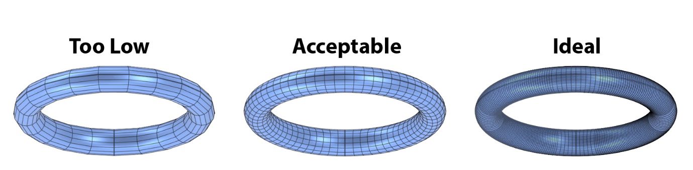
When saving your design for 3D printing, make sure the mesh is dense enough that individual mesh segments are not visible. If mesh density is too low, the casting will show the segmentation of the mesh.
Mesh and File Faults
Your 3D model must be a valid, closed mesh. A valid mesh should have none of the following:
- Intersecting faces.
- Degenerate faces.
- N-gons.
- Non-manifold edges.
- Naked edges.
- Duplicate faces.
Investment Breakage
Investment breakage occurs when fragments of investment break off and float around during casting, leading to porosity and surface defects. It is mainly caused by sharp edges, deep holes or thin, unsupported areas in the design.
Sharp Edges
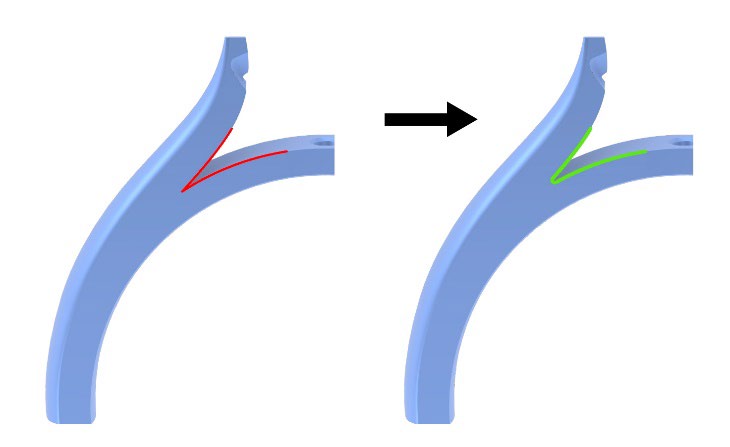
Add a small fillet to sharp edges. A fillet of 0.05 mm is usually enough to remove sharp, pointed areas.
Holes
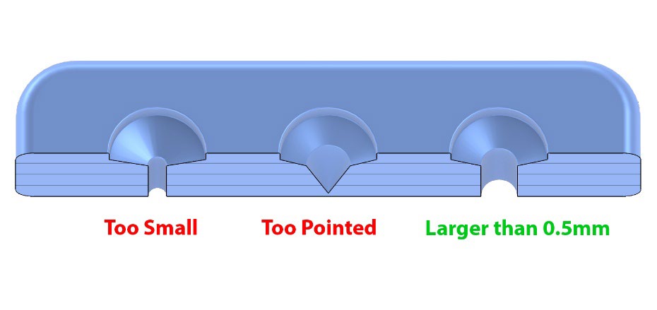
Holes must be larger than 0.5 mm in diameter, with the required diameter increasing in proportion to the thickness of the piece. For example, a 0.5 mm hole can be used in a 1 mm thick piece, while holes in a 3 mm thick piece should be at least 0.8 mm in diameter.
Gaps
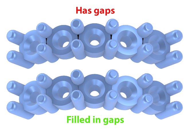
Fill in all small gaps that are less than 0.2 mm wide.
Material Thickness
- Minimum design thickness: 0.3–0.4 mm.
- Flat areas: at least 0.50 mm.
- Moulding: at least 0.90 mm.
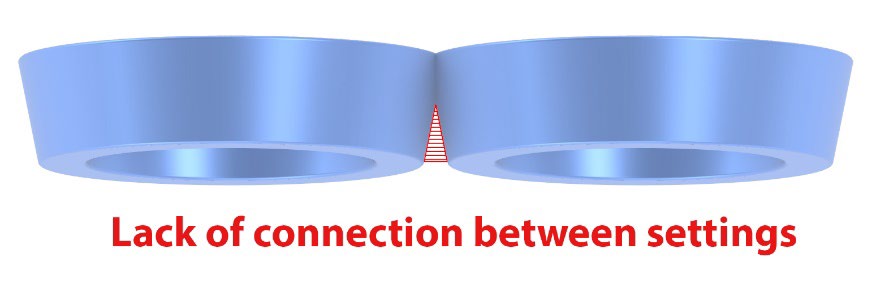
Connected Components
All parts of the design must connect to each other in a way that allows metal to flow into every area of the piece.
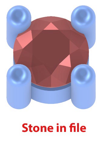
Remove Stones and Reference Files
Make sure stones and reference files are not included in the STL files.
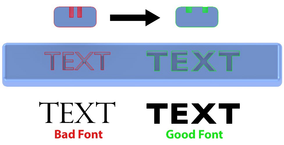
Text, Hallmarks and Lettering
- Use simple fonts without small serifs.
- Minimum width and spacing: at least 0.20 mm.
- Depth: no more than 0.30 mm, and no deeper than the opening width.
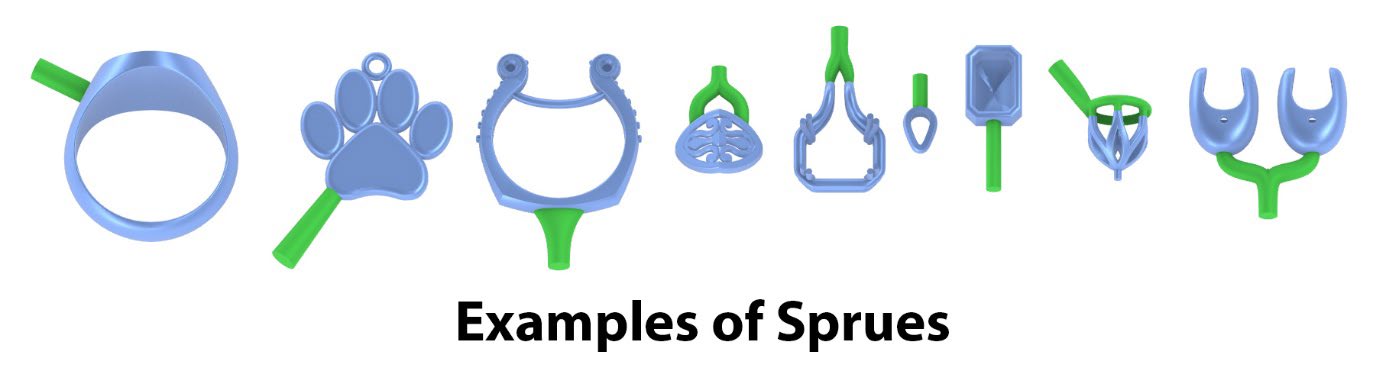
Spruing for Casting
Include a sprue in the STL design. The sprue size and dimensions depend on the thickness and size of the design; a diameter of approximately 2.0 mm is generally suitable for jewellery.
Consider how the design will be cast and place the sprue where it will work best.
Finishing and Shrinkage
Finishing removes 0.10–0.20 mm of surface material, so allow for this in the design. Also allow for shrinkage: larger pieces will have more shrinkage.
- Gold and silver: 0–1%.
- Platinum: 0–2%.
Need Help with Your CAD File?
Contact Us online, Ph 0800 881 888 or 09 638 7378.